

TL;DR
An automatic sliding door operator kit normally combines a motor, controller, transmission, suspension hardware and track; the exact sensor and accessory package must be itemized. Choose it by matching that package to the door leaves, opening geometry, electrical supply and required user protection. The quotation should describe an installable configuration, including responsibilities for items supplied elsewhere.
For project inquiries, I would start with the entrance drawing and the delivery boundary. Two cartons can both be described as an operator kit while leaving the buyer with very different work before the door can enter service.
Open the quotation before opening the carton
Use the manufacturer’s component list as the starting inventory, then turn it into the order’s bill of materials. A bill of materials is the identified list of parts and quantities supplied for the approved configuration. Product photographs help explain the assembly, but quantities belong in that list.
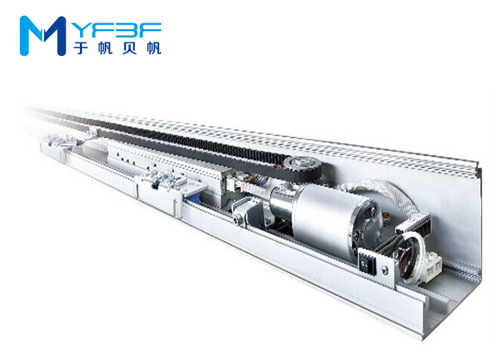
The YF150 sliding door operator product page publishes the following standard kit. Its overhead drive uses a geared motor and pulley to move a belt connected to the door.
| Component | Listed quantity | Role in the operator |
|---|---|---|
| Motor. | 1. | Drives the transmission. |
| Control unit. | 1. | Controls the operating sequence. |
| Power switch. | 1. | Provides the listed switching component. |
| Idler pulley. | 1. | Supports the belt path opposite the drive. |
| Hangers. | 4. | Suspend the moving leaves from the track. |
| Belt tooth clips. | 2. | Connect the moving arrangement to the belt. |
| Stoppers. | 2. | Provide mechanical travel stops. |
| Belt. | 1, 7 m. | Transmits motion along the operator. |
| 24GHz microwave sensors. | 2. | Provide the listed sensing devices. |
| Rail. | 1 set, 4.2 m. | Supports and guides the overhead moving hardware. |
Record part identities, configuration and substitutions alongside these quantities. In a double-leaf entrance, the arrangement of hangers and belt connections matters; a correct total count does not prove correct layout.
Door leaves, glazing, floor guides, structural fixings, locks and dedicated protective devices are not identified in that standard list. Establish their supply separately rather than assuming they arrive with the operator. Rail cover details, joining arrangements and any project-specific brackets also belong in the approved scope.
A complete entrance quotation must connect the operator package with the leaves, supporting structure, guidance and protective functions. This is the first useful difference between buying components for an experienced installer and buying a coordinated project package.
Fit the moving leaves to the entrance, not just the weight rating
Select the single- or double-leaf configuration before using the published capacity. A leaf is an individual moving door panel. The YF150 page lists a maximum of one 300 kg leaf for single operation and two 200 kg leaves for double operation.
These are different configurations, not permission to treat the double-leaf rating as one 400 kg panel. Include the actual panel construction and attached hardware in the weight assessment. For an unusually heavy or demanding arrangement, obtain a configuration review rather than relying on the model name.
The same page lists leaf widths of 700–1500 mm. Leaf width differs from clear opening, which is the unobstructed passage when the leaves are open. Overlap, fixed panels, travel and stop positions affect the relationship.
The listed 4.2 m rail and 7 m belt do not establish a 4.2 m or 7 m clear opening. Prepare a layout showing usable track length, hanger travel, pulley positions, end clearances and available pocket space. A rail length cannot replace that geometry review.
For a retrofit, examine the existing leaves and guidance before selecting a larger motor. Check alignment, rolling resistance, panel stability and the supporting header. The header is the structure above the opening that carries the operator and its loads.
Because binding guides and misaligned suspension increase resistance, extra motor capacity can conceal a mechanical problem without correcting it. My preference is to resolve the sliding geometry first. The operator should move a suitable door assembly, not force a poorly aligned one through its travel.
Read the electrical ratings at the right boundary
The YF150 motor’s 24 V rating and the operator’s AC input rating describe different parts of the system. The page specifies a 24 V, 60 W brushless DC motor and an AC 90–250 V, 50–60 Hz input.
Do not infer that the complete kit connects directly to a 24 V supply, or that the motor connects to mains. Match the supplied controller and power arrangement to the installation documentation. The 60 W motor figure also does not define every accessory load or the complete system’s input consumption.
Prepare an interface list for the motor, sensors, lock and access-control equipment. Record supply requirements, signal type, connector or terminal arrangement and the intended function. A voltage output and a voltage-free contact are different interfaces; similar wire counts do not establish compatibility.
The YF150 page lists adjustable opening speeds of 150–500 mm/s and closing speeds of 100–450 mm/s. These ranges describe adjustment capability. The commissioned settings must suit the installed leaves, protective arrangement and applicable requirements.
Because moving mass and speed affect the stopping task, the highest available speed is not automatically the appropriate project setting. Evaluate acceleration, deceleration and the approach to the end positions with the completed assembly, rather than choosing speed from a catalog range alone.
Ask each sensor what it is supposed to do
An opening command and protection of a person in the doorway are separate functions. Activation requests movement when someone approaches. Presence protection detects someone occupying a protected area and influences the door’s response while that area is occupied.
YF150′s two listed microwave sensors do not, by that description alone, establish the complete presence-protection arrangement. The sensor model, detection capability, coverage and connection to the controller matter. Avoid turning the phrase “sensors included” into an assumed safety specification.
For an example of the distinction, BEA’s IXIO-DT1 description identifies microwave activation and infrared presence detection as separate functions combined in one device. That example explains the functions; it is not a statement that this sensor is included with, or approved for, YF150.
Because triggering on approach does not demonstrate detection of someone remaining in the protected zone, an activation test cannot substitute for a presence-protection test. The project needs defined coverage at the relevant closing and opening hazards, with the specified controller response.
Also establish whether the controller and chosen protective devices support the required monitoring. Monitoring checks the protective system’s condition; its wiring and failure response need to be compatible. Do not assume any device with a relay output provides that function.
The product page describes reversal on obstruction. Treat that as one operating feature, not evidence that all required protective functions are covered. I would leave a safety-device substitution unapproved until its interface, coverage and system response have been reviewed.
Decide the power-failure and locking sequence together
Backup power is an optional configuration on the YF150 page, not part of its published standard inventory. If required, specify what it must accomplish: continued operation, movement to a defined position, or another approved sequence.
State the expected behavior on mains failure, depleted backup supply, alarm input and power restoration. Include the lock state and the permitted method of manual operation. A battery sized for one intended action should not be described as providing an unspecified period of normal service.
Because an engaged lock can prevent the intended movement, backup motor power alone does not establish an effective emergency-opening arrangement. Review the lock, release logic and operator sequence as a system. Access control should not silently override the entrance’s required exit behavior.
For applicable U.S. projects, the Access Board’s ADA provisions for automatic doors address power-on and power-off clear opening and contain conditions concerning accessible egress and standby power. That illustrates why choosing a battery is a project-design decision. The applicable building and exit requirements still determine the approved arrangement.
If the entrance requires a breakout function, fire/smoke performance or another specialized function, identify it before selecting the package. Breakout means a designed emergency opening mode of the doorset; it cannot be created merely by adding a battery to an ordinary sliding operator.
Specify the completed doorset’s acceptance basis
A functioning operator on a demonstration rail does not establish acceptance of the installed pedestrian entrance. The doorset includes the leaves, frame, operating equipment and the components that make them work together. Its assessment must address the actual installation.
BHMA’s overview of ANSI/BHMA A156.10-2024 identifies power-operated pedestrian-door requirements intended to reduce injury and entrapment. For projects using the European standard framework, BSI lists BS EN 16005:2023+A1:2024 for safety in use and test methods for power-operated pedestrian doorsets, including sliding types.
Use the requirements and editions specified for the destination and project. Publication of a newer edition does not itself update an existing legal reference. A generic certificate description on an operator page does not demonstrate that every assembled entrance meets the relevant requirements.
Commissioning means checking and setting the installed system before service. Its record should cover smooth movement, the required detection zones, response to protective inputs, operating modes, locking, power loss and restoration. Applicable measurements, signage and documentation should form part of the handover.
Assign responsibility for this work before dispatch. A distributor supplying components and a contractor delivering a commissioned entrance have different scopes. The purchase agreement should identify the handover point, installer qualifications and the documents each party must provide.
Choose the supply scope your team can support
Choose a component kit when your team can engineer the interfaces and complete the installation; choose a coordinated package when those responsibilities need to be supplied together. The relevant comparison is the work required to deliver the approved entrance.
For component supply, retain the approved drawings, controller configuration, sensor identities and part numbers. For a coordinated package, include leaves or their approved interfaces, guides, fixings, protective devices and commissioning responsibilities as applicable. Compare quotations against the same scope.
Plan service access to the header and identify replaceable belts, rollers, controllers and sensors. A spare part should match the installed version and configuration; an interchangeable-looking controller can change input behavior or setup requirements.
Review rail packaging and transport lengths alongside the installation plan. Define any permitted cut-to-length work and rail joints through approved instructions. Unplanned site modifications can affect alignment and serviceability even when all the cartons arrive.
Use our automatic sliding door operator selection to compare product families after the entrance requirements are defined. Move to another operator or a specialized doorset when the geometry, duty, environment or required function falls outside the proposed configuration.
Questions that often remain after selecting a model
Can I reuse an existing floor guide?
Only after checking its compatibility, condition and position with the proposed leaf arrangement. Wear or misalignment can affect movement even when the overhead operator is new.
Does self-learning remove the need for commissioning?
No. It may support setup, but it does not establish detection coverage, lock sequencing or the installation’s acceptance. Retain the required commissioning checks and records.
Can one kit serve both single- and double-leaf projects?
The YF150 page publishes ratings for both arrangements. Identify the actual configuration and layout in the order rather than assuming the same assembly settings suit both.
Does a longer hold-open time replace presence protection?
No. A time delay is not a record of whether someone remains in the protected area. Define the required detection and response independently.
Can I use a cheaper sensor with the same connector?
Connector fit alone is insufficient. Compare supply, signals, detection function, monitoring and compatibility with the approved protective arrangement.
What should an OEM sample demonstrate?
It should demonstrate the agreed configuration and interfaces under representative conditions. Keep the tested controller, motor, sensors and mechanical arrangement identified so production substitutions receive appropriate review.
Send the entrance drawing with the kit inquiry
Provide leaf quantities, individual weights and dimensions, clear opening, header layout, electrical supply and required operating modes with the inquiry. Include the destination and emergency-behavior requirements, then ask our engineers to identify the proposed operator, accessories and supply boundary. An itemized response is the basis for choosing a package your project can install, commission and support.
Post time: Nov-19-2026