

Card reader compatibility with automatic door operators is won or lost at three points: protocol, wiring, and relay timing. Get these right and the integration takes 90 minutes — get them wrong and you will chase intermittent failures for weeks.
TL;DR — Key Integration Points
- Wiegand is still the default protocol for 85%+ of installed card readers — but OSDP is gaining ground in new installations for its encryption and bidirectional communication.
- The relay output on the access controller must match the door operator’s trigger input type — dry contact (NO/NC) versus powered output, and the timing pulse width must be configurable between 0.5 and 30 seconds.
- Three wiring configurations cover 95% of integration scenarios: direct relay trigger, controller-managed hold-open, and fail-safe/fail-secure bypass for fire alarm integration.
- Our YF150 automatic sliding door operator accepts a standard dry contact trigger with adjustable hold-open timing from 0 to 60 seconds, making it compatible with virtually every access control system on the market.
Why Access Control Integration Fails — And Why It Is Rarely the Door Operator’s Fault
My name is Edison, and I manage global project inquiries and OEM/ODM custom solutions at Ningbo Yufan Beifan Automatic Door Co., Ltd. I have spent over a decade helping distributors and project procurement clients integrate automatic door operators with access control systems — card readers, biometric scanners, keypad entry systems, and intercom-based door release units. In that time, I have seen the same integration problems repeat across hundreds of projects, regardless of whether the access controller is a $200 HID EdgeReader or a $5,000 LenelS2 enterprise panel.
The pattern is always the same: the installer connects the card reader output to the door operator input. It works during commissioning. Three weeks later, the door intermittently fails to open on a valid credential — or worse, stays open indefinitely. The building owner blames the door operator. A technician is dispatched. The door operator tests perfectly in isolation. Because the problem is intermittent and the door operator passes every standalone diagnostic, therefore the root cause — a wiring, protocol, or timing mismatch at the integration boundary — goes undiagnosed for weeks.
I want to walk through exactly how to prevent this. What follows is the integration reference I send to every installer before they connect a card reader to our YF150 automatic sliding door operator — or any automatic door operator, for that matter. Because the signal interface between access control and door automation is standardized across the industry, therefore the principles here apply regardless of which manufacturer’s equipment you are using.
The Three Integration Interfaces: Protocol, Wiring, and Timing
Every card reader-to-door operator integration involves three distinct interfaces. They must all be correct for the system to work reliably. I will address each one in detail.
Interface #1: Protocol — Wiegand vs. OSDP vs. RS-485
The protocol determines how the card reader communicates with the access controller — and, downstream, how the access controller signals the door operator to open. Because Wiegand has been the dominant access control protocol since the 1980s, therefore approximately 85% of installed card readers in commercial buildings still use Wiegand. It is a simple, unidirectional protocol: the reader sends credential data to the controller over a DATA0/DATA1 wire pair. The controller authenticates the credential and energizes a relay output. The door operator sees the relay closure and opens.
Wiegand’s simplicity is its strength — and its weakness. It transmits credential data in plain text, has no encryption, and provides no feedback from the controller to the reader. If the reader is tampered with or the wiring is compromised, the controller may never know. This is why SIA (Security Industry Association) developed OSDP (Open Supervised Device Protocol), which uses RS-485 two-wire communication with AES-128 encryption and bidirectional supervision.
For the door operator integrator, the protocol distinction matters in one specific way: OSDP controllers can report door position status back to the access control system. If the door operator has a door position sensor output (our YF150 does — a magnetically-actuated reed switch that closes when the door reaches the fully open position), an OSDP controller can monitor whether the door actually opened after a valid credential was presented. With Wiegand, the controller energizes the relay and assumes the door opened — it has no way to verify.
Interface #2: Wiring — Dry Contact, Powered Output, and the Three Standard Configurations
This is where I see the most field wiring errors. The access controller’s relay output and the door operator’s trigger input must agree on signal type. There are three standard configurations:
Configuration A: Dry Contact, Normally Open (NO) — The Universal Standard. The access controller provides a voltage-free relay contact that closes momentarily (typically 1-5 seconds) upon valid credential read. The door operator’s trigger input is configured for dry contact closure. When the relay closes, the door operator sees the contact closure and initiates an open cycle. This is the configuration used by approximately 80% of installations and is supported by every automatic door operator I have ever encountered, including all models in our YFBF product range.
The wiring is straightforward: two conductors from the access controller’s relay output (NO and COM) to the door operator’s trigger input terminals. That is it. Because the relay provides galvanic isolation between the access controller and the door operator, therefore ground loops, voltage mismatches, and electrical noise coupling — the three most common sources of intermittent integration failures — are eliminated by this configuration.
Configuration B: Powered Output (12V or 24V DC). Some access controllers — particularly older models and certain intercom-based entry systems — output a powered signal instead of a dry contact. For example, the controller applies 12V DC to a trigger wire for the duration of the unlock period. If the door operator is configured for dry contact input and receives a powered signal, the result can range from intermittent operation to permanent damage of the input circuit. I have replaced three door operator control boards in the past two years because installers connected a powered output to a dry-contact input without checking the voltage.
Configuration C: Fail-Safe / Fail-Secure with Fire Alarm Override. In commercial buildings, the fire alarm system must be able to override access control and force doors open for egress. This requires a separate trigger input on the door operator — a fire alarm interface (FAI) terminal that, when energized or de-energized (depending on configuration), forces the door to open and remain open until the fire alarm condition clears. Because fire codes in most jurisdictions require that automatic doors default to the open position upon fire alarm activation, therefore the FAI wiring must be verified during commissioning with an actual fire alarm test — not just a continuity check. The National Fire Protection Association standard NFPA 101 Life Safety Code governs these requirements in the United States, and equivalent standards apply in other jurisdictions.

Interface #3: Timing — Relay Pulse Width and Hold-Open Duration
The timing interface is the most overlooked variable in access control integration — and the one that generates the most service calls. There are two timing parameters that must be coordinated:
Access controller relay pulse width: This is how long the controller's relay remains closed after a valid credential read. Typical factory defaults are 1, 3, 5, or 10 seconds — and the value is almost always configurable in the controller's programming software. If the pulse width is too short, the door operator may not register the trigger. Our YF150 requires a minimum trigger pulse of 100 milliseconds (0.1 seconds), which is well below any realistic controller pulse width — but I have encountered controllers where the pulse width was accidentally set to 50 milliseconds during programming, and the door operator never responded.
Door operator hold-open time: This is how long the door remains open after receiving a trigger signal, before beginning its close cycle. On our YF150, this is adjustable from 0 to 60 seconds via a potentiometer on the control board. The correct hold-open time depends on the application: 3-5 seconds for a standard office entrance where people walk through at normal speed, 10-15 seconds for wheelchair-accessible entrances per ADA guidelines, and 20-30 seconds for freight or hospital corridor doors where gurneys and equipment carts need time to clear the threshold.
Because the access controller's relay pulse and the door operator's hold-open timer are set independently and often by different technicians, therefore I recommend documenting both settings in the commissioning report and attaching a label inside the door operator housing. When a service call comes in six months later — "the door stays open too long" or "the door doesn't always open on the first badge tap" — the technician can check the documented settings against the current configuration in under two minutes.
Wiring Reference: Connecting the YF150 to Common Access Controllers
I want to provide a specific wiring reference for our YF150 operator, because I field these questions every week. The YF150 control board has a dedicated trigger input terminal block with clearly labeled connections:
- OPEN — Trigger input for door open signal (dry contact closure between OPEN and GND)
- GND — Signal ground reference
- LOCK — Door lock relay output (energized when door is closed, for electromagnetic lock integration)
- FAI — Fire alarm interface input (forces door open when triggered)
- POS — Door position sensor output (reed switch, closed when door reaches fully open)
For a standard access control integration with a dry contact relay output, the wiring is two conductors: controller NO → YF150 OPEN, controller COM → YF150 GND. That is the complete wiring diagram for 80% of installations.
For installations requiring fire alarm integration, connect the fire alarm control panel's relay output to the YF150 FAI terminal. When the fire alarm relay closes (or opens, depending on configuration), the YF150 forces the door to open and disables the automatic close function until the fire alarm condition is cleared. Because fire alarm wiring must be supervised for integrity — a broken wire must trigger a fault indication at the fire alarm panel, therefore the FAI connection must use end-of-line (EOL) resistor supervision per the fire alarm system design. I recommend coordinating this wiring with the fire alarm contractor during rough-in, not after the door operator is installed.
Common Troubleshooting Scenarios and Their Root Causes
Over the years, I have compiled a mental database of access control integration failures and their most probable causes. Here are the four scenarios I see most frequently:
Symptom: Door opens on some badge reads but not others. The most likely cause is electrical noise on the trigger wiring — especially if the trigger cable runs parallel to AC power wiring for more than 10 feet (3 meters). Because the YF150 trigger input is edge-sensitive (it detects the transition from open circuit to closed circuit), therefore a noise spike on the trigger line can be interpreted as a valid trigger — or, more commonly, can mask a real trigger. The fix is to use shielded cable for trigger wiring, with the shield drain wire connected to ground at the controller end only. Alternatively, if re-wiring is impractical, add a 0.1 µF ceramic capacitor across the OPEN and GND terminals at the door operator to filter high-frequency noise.
Symptom: Door opens normally but never closes. Check the hold-open timer setting first. If it is set to maximum (60 seconds on our YF150), reduce it to the appropriate value for the application. If the timer is set correctly and the door still does not close, check for an active safety sensor signal. Because the YF150's safety beam sensor overrides the close cycle — if the sensor detects an obstruction, the door will not close regardless of timer setting, therefore a misaligned or dirty safety sensor is the second most common cause of "door won't close" service calls. Clean the sensor lenses with isopropyl alcohol and verify alignment with the reflector or receiver.
Symptom: Door opens immediately on power-up without any badge read. This almost always indicates that the trigger input wiring is shorted — either a staple or drywall screw has penetrated the cable, or the access controller's relay is stuck closed. Disconnect the trigger wires at the YF150 terminal block. If the door stops opening on power-up, the problem is in the access controller or the wiring. If the door continues to open on power-up with the trigger wires disconnected, the YF150 control board has a fault — contact our technical support team. Because a shorted trigger input is electrically identical to a valid trigger signal, therefore the door operator cannot distinguish between the two — and the only way to isolate the fault is to disconnect the trigger wiring at the door operator and test each component separately.
Symptom: Intermittent operation that correlates with weather. I see this most often in exterior entrances where the access controller is mounted in an unheated vestibule. Because condensation forms on relay contacts when warm, humid air meets cold metal surfaces, therefore relay contacts in exterior-mounted controllers can develop high-resistance oxidation that produces intermittent contact closure. The fix is to specify access controllers with sealed, gas-filled relays (hermetically sealed) for exterior installations, or to install a small thermostatically-controlled enclosure heater to keep the controller above the dew point.
Future-Proofing: Planning Your Access Control Integration for OSDP and Mobile Credentials
I am increasingly asked by project specifiers: "Should we still install Wiegand readers, or should we future-proof with OSDP?" My answer depends on the project timeline and the building's security requirements.
If the building opens in the next 12 months and the security requirement is straightforward — employee badge access during business hours, no audit trail requirements beyond basic time-and-attendance — Wiegand is still a completely valid choice. The hardware is less expensive, every access control technician knows how to install it, and it works reliably with every automatic door operator on the market.
However, if the project has a 24-month timeline, if the security specification requires encrypted communication, or if the building owner wants to support mobile credentials (smartphone-based access via NFC or Bluetooth), I strongly recommend specifying OSDP. Because OSDP readers and controllers are backward-compatible with Wiegand wiring — the same 4-conductor cable that carries Wiegand can be re-terminated for OSDP RS-485, therefore the wiring infrastructure investment is identical. The cost difference is in the reader and controller hardware, which is narrowing: OSDP readers now cost approximately 15-25% more than equivalent Wiegand readers, down from 40-50% three years ago.
For the door operator side, the integration does not change. Whether the access controller speaks Wiegand or OSDP, it still outputs a dry contact relay closure to trigger the door operator. That relay closure is electrically identical regardless of the upstream protocol. Because the door operator only sees the relay output — not the protocol, therefore your choice of Wiegand vs. OSDP has zero impact on door operator compatibility. This is the question I answer most frequently, and the answer is always the same: the door operator does not care.
Frequently Asked Questions
Do your automatic door operators work with HID card readers?
Yes. Our YF150 and all YFBF automatic door operators accept a standard dry contact trigger input, which is compatible with every HID card reader configuration when paired with an access controller. The card reader communicates with the access controller via Wiegand or OSDP. The access controller energizes a relay output upon valid credential read. That relay closure triggers the door operator. At no point does the card reader communicate directly with the door operator — the access controller sits between them as the intermediary. Because the integration interface is a simple dry contact closure, therefore compatibility is universal across all card reader and access controller brands.
What is the minimum trigger pulse width your door operator requires?
Our YF150 and all current YFBF automatic door operator models require a minimum trigger pulse of 100 milliseconds (0.1 seconds). This is well below the factory default relay pulse width of virtually every access controller on the market, which typically defaults to 1-5 seconds. The only situation where pulse width becomes an issue is when a technician has manually reprogrammed the access controller to an unusually short relay time — we have seen cases of 50-millisecond pulses that our door operator did not register. The solution is to verify the access controller's relay pulse width setting is at least 200 milliseconds — double our minimum, to provide a safety margin.
Can your door operator interface with a fire alarm system for emergency egress?
Yes. All YFBF automatic door operators include a dedicated Fire Alarm Interface (FAI) input. When the FAI input is triggered, the door opens immediately and remains open until the fire alarm condition clears, overriding all other control inputs including the access controller and the hold-open timer. The FAI input can be configured for either normally-open or normally-closed supervision, depending on the fire alarm system design. Because fire alarm integration is a life safety function, therefore I recommend having the fire alarm contractor, not the door installer, make the final FAI connections and verify operation during the fire alarm system acceptance test. Compliance with NFPA 101 Life Safety Code (or local equivalent) must be verified by the authority having jurisdiction (AHJ).
What cable type do you recommend for trigger wiring between the access controller and the door operator?
I recommend 18-22 AWG shielded twisted-pair cable (Belden 8760 or equivalent) for all trigger wiring runs. The shield drain wire should be connected to ground at the access controller end only — connecting the shield at both ends creates a ground loop that couples noise into the signal conductors. For runs under 50 feet (15 meters), unshielded cable is acceptable, but I still recommend shielded cable because the incremental cost is approximately $0.15 per foot and it eliminates noise-related service calls. Because trigger wiring is low-voltage (typically 12-24V DC) and carries no significant current, therefore 22 AWG conductors are adequate for runs up to 1,000 feet (300 meters). For longer runs, use 18 AWG to ensure the voltage drop does not affect the relay closure detection threshold.
Can I connect multiple door operators to a single access controller output?
Yes — with one critical constraint. The access controller's relay output must be rated for the combined inrush current of all connected door operator trigger inputs. Our YF150 trigger input draws approximately 5 mA at 12V DC, so a single relay output can comfortably drive 10+ YF150 operators in parallel. However, if the door operators are from different manufacturers, verify each one's trigger input current draw and ensure the total does not exceed the relay contact rating. Because relay contacts have a minimum switching current as well as a maximum, therefore connecting only one door operator to a relay rated for 5A at 250V AC may actually cause contact oxidation — the 5 mA load is too low to provide the "wetting current" that keeps the relay contacts clean. For single-door installations with a high-current relay, add a 1 kΩ resistor in parallel with the door operator trigger input to increase the switching current to approximately 12 mA, which is sufficient to maintain clean relay contacts.
About the Author
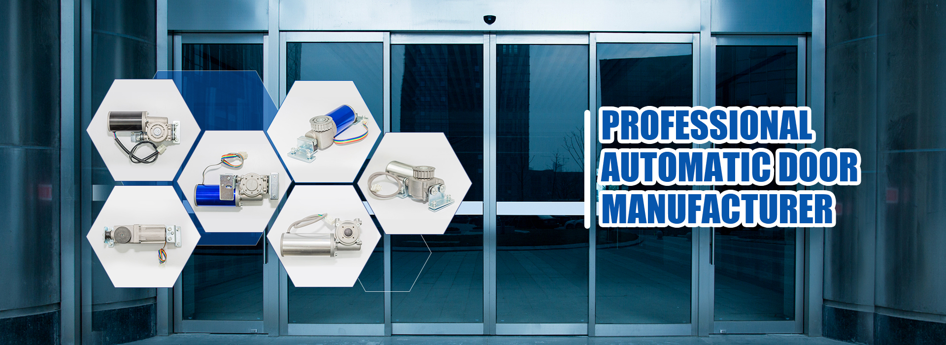
Edison is the Sales Manager at Ningbo Yufan Beifan Automatic Door Co., Ltd., specializing in automatic door system R&D and manufacturing. Core products include automatic sliding door operators, 24V brushless DC door motors, and accessories, widely used in commercial buildings, public facilities, and industrial sites.
Edison manages global project inquiries and OEM/ODM custom solutions, supporting distributors and project procurement clients worldwide. YFBF's flagship YF150 automatic sliding door operator features a 24V brushless DC motor with integrated access control interface, adjustable hold-open timing, and fire alarm integration — engineered for reliable performance in high-traffic commercial environments. Explore the full product range at yfbfautomaticdoor.com/products.
Post time: Jun-26-2026