

TL;DR
An automatic sliding door install is a four-step sequence on site: (1) survey the opening to confirm door-leaf weight, leaf width, traffic direction and the available header depth, (2) prepare the header with the track, mounting surface, motor cable and sensor conduit, (3) mount the operator and motor unit and align the belt drive, then (4) wire the control unit, microwave sensors, backup battery and ground, run the commissioning checklist, and hand over to the client. For commercial sites the most-installed unit in the Yufan Beifan line is the YF200 heavy-duty sliding door operator — 24 V 60 W brushless DC motor, 1×300 kg single-leaf or 2×200 kg double-leaf, 700–1500 mm leaf width, opening speed 150–500 mm/s, AC 90–250 V input, operating temperature -20°C to +70°C. This contractor-side walk-through covers the eight stations on site that determine whether the install passes inspection on first visit.
What an Automatic Sliding Door System Actually Includes
Before the first bracket goes up, the contractor should be clear on what arrives in the crate. A complete automatic sliding door system has four subsystems, each with its own install step:
- Track and header assembly — the aluminium header that spans the door opening, the belt-driven track, the idler pulley, the belt, the belt-tooth clips, and the stoppers. Header length is typically 2× the door-leaf width plus 200–400 mm clearance. – Operator and motor unit — the gearbox, the 24 V brushless DC motor, the control unit, the power switch, and the mounting hangers. For commercial heavy-duty installs this is the YF200 automatic sliding door operator at 1×300 kg single-leaf or 2×200 kg double-leaf capacity. – Sensors and activation — dual 24 GHz microwave motion sensors, an optional infrared safety sensor on the closing edge, an activation switch (radar, push-button, access-control reader, or push-pad), and the wiring loom. – Power and backup — the AC 90–250 V supply input, the 24 V DC rail after the internal SMPS, the backup battery pack (usually 12 V 4–7 Ah sealed lead-acid) for power-loss operation, and the earthing lug.
For slim-frame or full-glass openings the BF150 automatic sliding door operator is the alternative — same control logic and same sensor interface, narrower motor housing for frameless glass. The slim-frame variant is interchangeable on the wiring and commissioning side; the mechanical mounting differs. The Ningbo Yufan Beifan engineering group supports both product lines from the same Ningbo HQ facility and the same Ningbo Jingyi Group export channel used by audio and electronics OEM buyers. The frameless-glass mounting pattern is documented in the US Glass Association installation handbook and the European Glass Industry Association technical bulletins for full-glass commercial entrance assemblies.
| Operator unit | Max leaf weight (single / double) | Leaf width | Best-fit application |
|---|---|---|---|
| BF150 slim-frame | 1×120 kg / 2×80 kg | 600–1200 mm | Full-glass frameless shopfronts |
| YF150 standard | 1×150 kg / 2×120 kg | 650–1300 mm | Light commercial (retail, clinic) |
| YF200 heavy-duty | 1×300 kg / 2×200 kg | 700–1500 mm | Hotel, airport, hospital, rail |
| YFSW200 swing-door | 1×200 kg per leaf | 750–1500 mm | Swing entrances, accessibility |
Standard kit checklist for a YF200 install, per the production specification sheet: 1× motor unit, 1× control unit, 1× power switch, 1× idler pulley, 4× hangers, 2× belt-tooth clips, 2× stoppers, 7 m of belt, 2× 24 GHz microwave sensors, 1× set of 4.2 m rail. Add backup battery (typically a 12 V 5–7 Ah SLA or 12 V LiFePO4 replacement) and the optional infrared safety beam if the door face is below 2.5 m above the floor. The presence-detection overlay, where required by local code, is supplied separately based on the ANSI/BHMA A156.10 presence-sensor spec or the equivalent EN 16005 clause. The sensor selection — dual 24 GHz microwave for activation, photoelectric or passive-infrared for the closing-edge safety overlay — is the IEC 60335-2-103 baseline pattern; the equivalent US specification is in UL 325 clause for door operators with a separate presence-detector input.
Pre-Install Site Survey — Five Measurements That Decide the Whole Job
The site survey is the single step that determines whether the install passes inspection on the first visit or whether the crew is back on Monday pulling brackets. Five measurements, taken in order:
1. Door-leaf weight (single or double). This selects the operator unit. Below 150 kg per leaf any unit in the sliding door operator line handles it; above 150 kg, up to 300 kg single-leaf, the YF200 is the correct pick. Above 300 kg a swing-door opener or a heavier commercial operator is required. Industry guidance on commercial entrance weight classes is summarized by the BHMA load-class table and the European EN 16005 door-mass envelope. 2. Door-leaf width. YF200 spec window is 700–1500 mm per leaf. Measure the clear opening at three points (top, middle, bottom) and use the largest figure. Frames out of square by more than 5 mm across the opening need shimming on the track side. 3. Header depth and clear height. The operator unit adds 180–220 mm of header depth. Verify that the structural lintel above the opening can accommodate this without intruding on the fire-rated ceiling assembly below. Header clear height inside should be ≥ 220 mm to clear the motor housing and allow belt-tensioning access. 4. Traffic direction and approach path. Microwave sensor throw pattern is asymmetric — typically a 2.5 m forward lobe and a 0.8 m side lobe. Walk the approach path with the client and identify where the radar will and will not trigger. For double-leaf doors with two-way traffic, both leaves need sensor coverage on both sides. 5. Power supply and earthing point. The operator accepts AC 90–250 V, 50–60 Hz. Confirm a dedicated 10 A breaker on the distribution board, a verified earth at the header, and cable routing that keeps the 230 V mains separated from the 24 V control loom by at least 150 mm.
Field note: roughly 30% of “operator doesn’t work” warranty returns are traced to the site survey step — wrong leaf weight class, missing earth, or sensor mounted across a metal door frame that blocked the radar lobe. Every measurement above is documented on the install checklist before the bracket goes up. Cross-reference the site-survey record against the relevant OSHA pedestrian-door safety guidance, the NFPA 101 emergency-egress provisions, and the US Department of Energy commercial-buildings efficiency programme when the door serves an egress path or a high-traffic public entrance.
Header Preparation — Track, Mounting Surface and Cable Routing
The header must be structurally sound, plumb, and able to carry the door-leaf weight across the full opening with a deflection budget under 2 mm at full load. On new-build sites the header is part of the structural frame; on retrofit sites the contractor typically bolts a steel or aluminium sub-frame to the existing lintel and hangs the operator header from that sub-frame.
The track is the first element to install on the header. It must be level to within ±1.5 mm across the full length. Out-of-level track shows up as bind-and-stall in the mid-leaf position, typically around the 50% open point where the leaf load shifts from the operator pulley to the idler. Shim the track at every fixing point; do not rely on the bracket flexibility alone.
Cable routing follows the same step. The standard kit ships with a 7 m belt and the motor cable is roughly 1.5 m. The contractor routes the motor cable inside the header to the control-unit location (typically on the side opposite the motor pulley), drops the sensor cable down the non-opening jamb, and brings the AC mains in from above via a fused spur or junction box. Three rules on cable routing: keep 230 V mains at least 150 mm from any 24 V control cable, do not run control cables parallel to the AC mains for more than 1.5 m, and provide strain relief at every cable transit. The cabling spec is documented in the YF200 wiring diagram shipped with every production lot.
Operator Unit and Motor Mounting — Mechanical Alignment
The operator unit hangs from the header on four hangers, two per side. Lift the unit into the header cavity, position the motor pulley at the end opposite the idler pulley (typically the lock-side jamb), and bolt the hangers to the header through the existing mounting holes. Do not drill new holes in the operator housing — that voids the warranty on the YF200 unit.
Belt installation is the mechanical alignment step that determines smooth-running versus noisy. The belt clips to the door-leaf carrier at the tooth-clip position, runs along the underside of the track to the motor pulley, wraps the motor pulley 180°, and returns along the inside of the track to the idler pulley. Belt tension is set by the idler-pulley adjustment screw. The correct tension is 8–12 mm of mid-span deflection when the belt is pushed with 5 kg of force at the midpoint. Over-tensioned belts cause premature pulley-bearing wear; under-tensioned belts cause the door leaf to lag during the open cycle and to jerk on the close cycle.
Door-leaf hanging follows the belt attachment. The leaf carrier attaches to the top of the door leaf via the hanger bolts, with the leaf hanging plumb. Adjust the hanger height so the leaf floor clearance is 8–12 mm and the leaf-to-frame gap on the closing side is 5–8 mm. Out-of-plumb leaves bind against the side frame and produce a thump at end-of-cycle; the symptom is often misdiagnosed as a sensor fault.
Wiring the Operator, Control Unit, Sensors and Backup Battery
The wiring step is where most first-time installers go wrong, and where the commissioning team spends the most hours on a warranty callback. The wiring sequence, in the order the production manual specifies:
1. AC mains input — connect AC 90–250 V live, neutral and earth to the marked terminals on the control unit. Verify the dedicated breaker, the earth continuity (≤ 0.5 Ω to the main earth bar), and the absence of voltage on the earth conductor before connecting. 2. 24 V DC rail — confirm the internal SMPS output is within 23.5–24.5 V DC under no load. The control unit will not power up the motor drive if the rail is outside this window. 3. Motor phase wiring — three-wire connector from the control unit to the brushless DC motor. Reversing any two wires reverses the motor direction; the commissioning step catches this, but it is cleaner to verify with a multimeter before first power-up. 4. Sensor wiring — 24 GHz microwave sensors have a four-wire interface (24 V DC, GND, signal, and shield). Wire the indoor-side sensor to the activation input and the outdoor-side sensor to the same activation input in parallel if two-way activation is required. The infrared safety beam (if fitted) connects to the safety input; reversing safety and activation produces a door that closes on the activation signal and ignores the safety stop. 5. Backup battery — 12 V SLA or LiFePO4 pack, fused at 5 A, wired to the battery terminals on the control unit. Verify the float-charge voltage is 13.6–13.8 V (SLA) or 14.0–14.4 V (LiFePO4). Out-of-spec float voltage destroys the battery within months. 6. Earth bond — bond the motor housing, the control-unit chassis, and the header frame to the main earth with a dedicated earth conductor. Do not rely on the mounting bolts for the earth path.
The full wiring diagram is in the YF200 product documentation pack, and the same wiring logic applies across the sliding door operator family with only the connector-shell keying differing between SKUs. The 24 V DC SELV (safety extra-low voltage) classification of the control rail is the basis for the IEC 60335-1 separation-distance rules cited in the wiring section above; the AC mains input and earthing follow IEC 60335-2-103 clause 6 for drives on building entrances, with US-market installs additionally governed by UL 325 and the NFPA 70 Naationl Electrical Code conductor-sizing tables.
Sensor Placement, Safety Overlay and Code-Compliance Handoff
Sensor placement is the safety-critical step. The 24 GHz microwave sensor activates the door when a person or object moves into its detection lobe. Mounting height above the floor is typically 2.2–2.5 m; mounting too low catches the door leaf as it passes; mounting too high misses children and short adults. The detection lobe projection should clear the door leaf in the fully open position by at least 300 mm, otherwise the door re-triggers on its own opening leaf and the system faults out.
The safety overlay for automatic sliding doors in most jurisdictions is the EN 16005 / EN 16361 standard for European installs, or the ANSI/BHMA A156.10 standard for US installs. Both require a combination of activation sensors and a presence-detection safety system on the closing edge of the door leaf. The presence detector is typically a passive infrared curtain or a through-beam photoelectric pair. Without the presence detector the install does not pass inspection in any EU member state or in any US state that has adopted ANSI A156.10. The European Committee for Standardization (CEN TC 33) maintains the EN 16005 and the related EN 16361 product standard; the US Builders Hardware Manufacturers Association (BHMA) maintains the A156 series and the certification program that most US inspectors reference. Electromagnetic compatibility and operator safety are covered by the IEC 60335-1 and IEC 60335-2-103 standards, and US-market installs additionally reference UL 325 on door, drapery, and window operators and systems.
Source the operator unit and accessories for your next automatic sliding door install
Yufan Beifan Automatic Door supports contractors and project procurement with the YF200 heavy-duty sliding door operator, the BF150 slim-frame variant, and the full accessories kit (rail, hanger, belt, sensor, control unit, backup battery). Send your door-leaf weight and width, the daily cycle count, and the destination country and the engineering team returns the matched SKU, the wiring diagram, and the lead time.
Frequently Asked Questions
A two-person crew with prior sliding-door experience installs a YF200 unit on a prepared opening in 5–7 working hours. The breakdown is roughly 1 hour for site survey and bracket layout, 1.5 hours for header preparation and track mounting, 1 hour for operator unit and motor mounting with belt alignment, 1 hour for wiring the control unit, sensors, and backup battery, 1 hour for the commissioning checklist and the ten sensor/safety tests, and 0.5 hour for documentation handover. On a retrofit site where the header is not pre-installed, add 2–3 hours for the structural sub-frame and cable routing. First-time installers typically budget a full 8-hour day per door.
The YF200 operator accepts AC 90–250 V, 50–60 Hz mains input directly via the internal switch-mode power supply (SMPS). The SMPS converts the AC mains to 24 V DC for the brushless DC motor and the control electronics. From the installer’s perspective, what matters is the dedicated 10 A breaker on the AC distribution board, the verified earth (≤ 0.5 Ω to the main earth bar), and the cable routing that keeps mains separated from low-voltage control wiring by at least 150 mm. Buildings with a DC microgrid or DC backup distribution require an inverter stage upstream of the operator; this is unusual in commercial sites and is handled by the electrical consultant on a project-by-project basis.
No. The YF200 is rated for 1×300 kg single-leaf or 2×200 kg double-leaf. Above 300 kg single-leaf the operator duty cycle, the motor torque, the belt pull force, and the gearbox all exceed design limits. For heavier commercial entrances — typically large airport, rail or industrial applications — a swing-door operator or a heavier-duty sliding-door drive is specified. The Yufan Beifan sliding door operator family tops out at the YF200; above that rating the conversation moves to custom engineering.
In the EU, the EN 16005 standard requires a combination of activation sensors (radar, push-button, or access-control reader) and a presence-detection safety system on the closing edge of the door leaf — typically a passive infrared curtain or a through-beam photoelectric pair. In the US, ANSI/BHMA A156.10 covers equivalent requirements and most US states adopt it. The presence detector must hold the door open for the full duration that a person or object remains in the closing path. The YF200 ships with two 24 GHz microwave activation sensors as standard; the presence-detection safety sensor is typically added to the order based on the installer’s site survey.
Industry practice is a six-month preventive-maintenance visit covering belt-tension check, idler-pulley bearing inspection, sensor coverage verification, safety-sensor test, backup-battery capacity test, and a full open-close cycle counter review. High-traffic sites (airport, rail, hospital) move to a three-month interval. The cycle counter on the YF200 control unit logs total cycles and power-loss events; the reading is included in the maintenance report. Belt replacement is typically required every 18–24 months on a 200-cycle-per-day site; sensor replacement is event-driven rather than interval-driven.
On a typical retail or hotel install running 100–200 cycles per day in a climate-controlled environment, the YF200 operator has a service life of 8–12 years before the gearbox brushes, the motor bearings, or the control-unit SMPS capacitors reach end-of-life. Service life is shorter — typically 5–7 years — in harsh environments with high humidity, salt temperature, or sustained high cycle counts above 500 per day. The most common wear items are the idler-pulley bearing (replace at 5 years), the belt (replace at 18–24 months), and the backup battery (replace at 3 years). All wear items are stocked as standard accessories alongside the operator unit.
Yes. The YF200 control unit has dry-contact inputs for activation (push-button, access-control reader, or radar) and dry-contact outputs for door-status reporting (open, closed, fault). The access-control integration is typically a relay output from the access controller wired to the activation input, and a door-position sensor (usually a magnetic reed switch on the header) wired back to the access controller for status logging. Building-management integration (BACnet, Modbus, or KNX) is handled via an optional protocol gateway; the gateway is ordered as a separate line item on the Yufan Beifan commercial quotes. The relevant building-automation standards for door-status reporting and integration are the BACnet standard AS and the KNX building-systems standard.
The YF200 ships with a backup-battery input that accepts a 12 V SLA or LiFePO4 pack, typically 5–7 Ah. On power loss the battery takes over within 1 second and runs at least 50 open-close cycles on a single charge. When the battery drops below the low-voltage cutoff, the operator defaults to manual-release mode — the door leaf can be slid by hand for emergency egress. The backup-battery voltage is logged on the control-unit fault log and on every preventive-maintenance visit. Most commercial sites replace the backup battery at the 3-year mark as a preventive measure rather than waiting for the low-capacity warning.
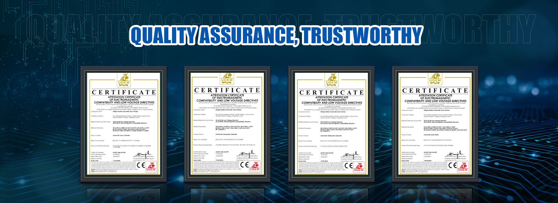
The Yufan Beifan export sales team handles project quotations directly. The YF200 product page carries the published specification, the standard kit contents, the wiring diagram, and the CE/ISO certification files for inclusion in the contractor’s compliance pack. Project pricing, OEM/ODM customisations, and on-site commissioning requests are handled through the contact channel, with a typical quote turnaround of 2–3 working days for stock SKUs and 5–7 working days for custom configurations. Lead time from Ningbo to most major ports is 15–25 days for Asia and the Middle East, 30–45 days for Europe, Africa, and Latin America. Cross-vertical project quotes across the Ningbo Jingyi Group — for example a hotel that needs both the YF200 operator and a Jingyi Audio pro audio cable installation — are coordinated on the same Ningbo export-team workflow. Code-compliance reference for the operator unit is the IEC 60335-2-103 standard and the European Committee for Standardization technical committee for EN 16005.
Post time: Sep-21-2026